

5.1 The accelerator
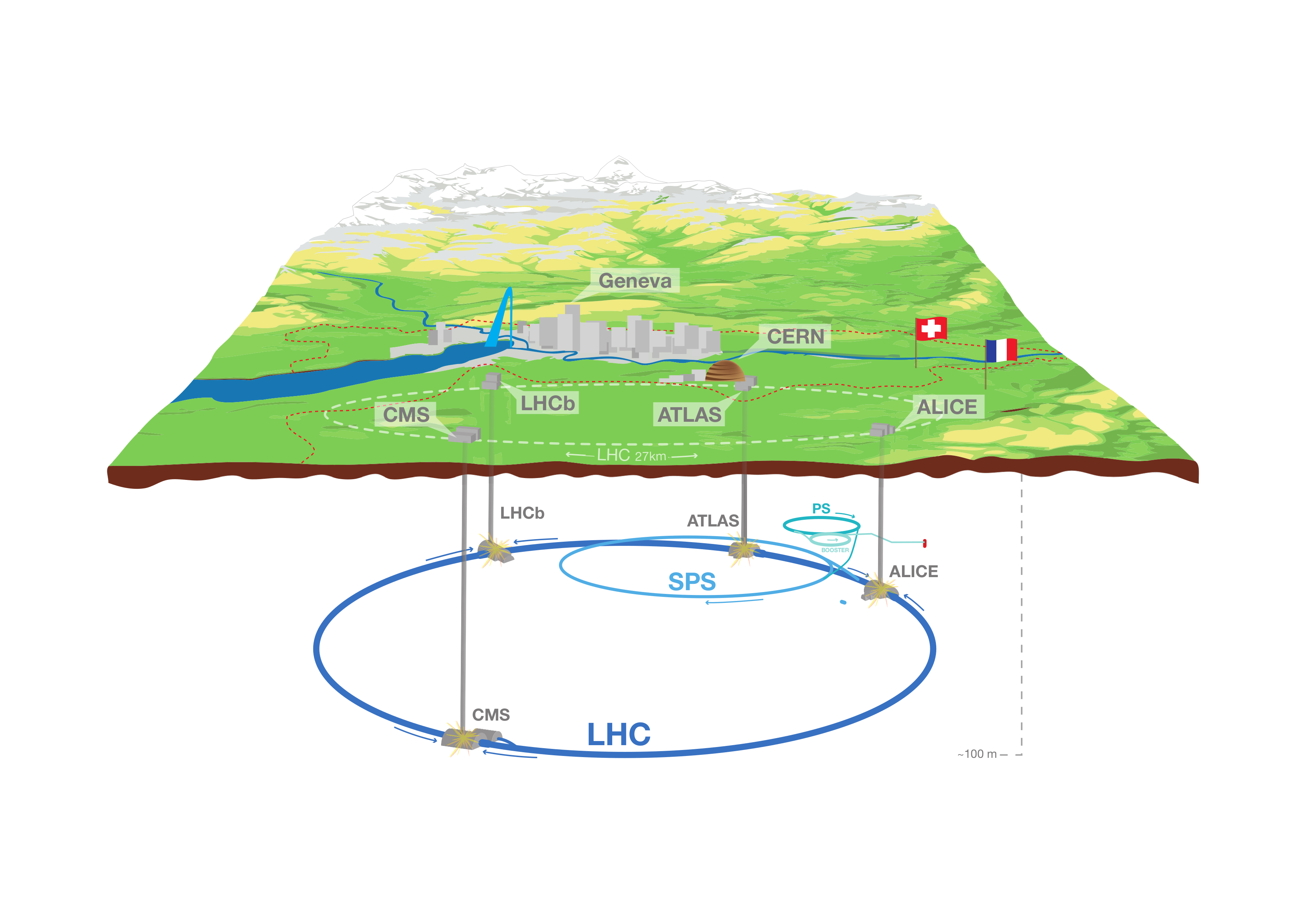
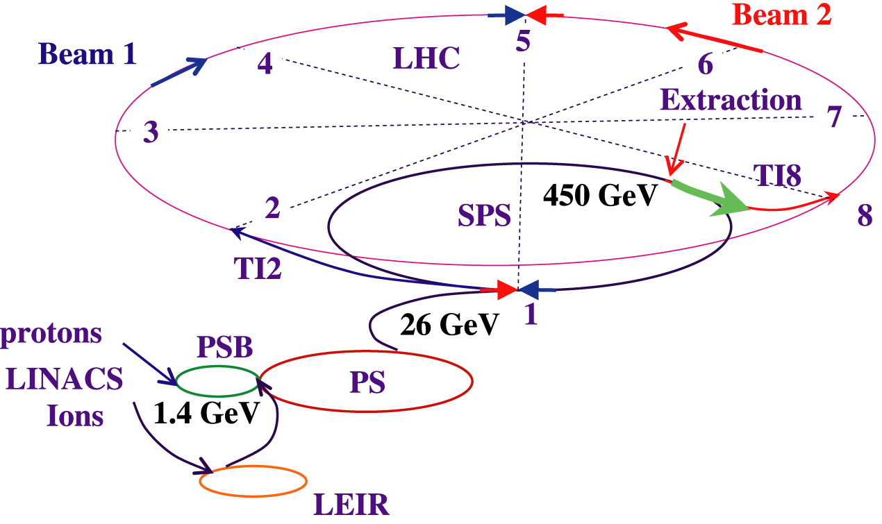
The overall LHC accelerator complex is shown in Figure 5.2. Protons are first extracted from a hydrogen gas bottle through a duoplasmatron ion source [170] as a low energy beam of around 100. They are then accelerated through a series of “injectors” (Figure 5.3): first through a linear accelerator (LINAC) up to 50; then a proton synchotron booster (PSB) up to 1.4; the proton synchotron (PS) up to 26; and finally through the super proton synchotron (SPS) up to 450, after which the protons are transferred to the LHC ring.
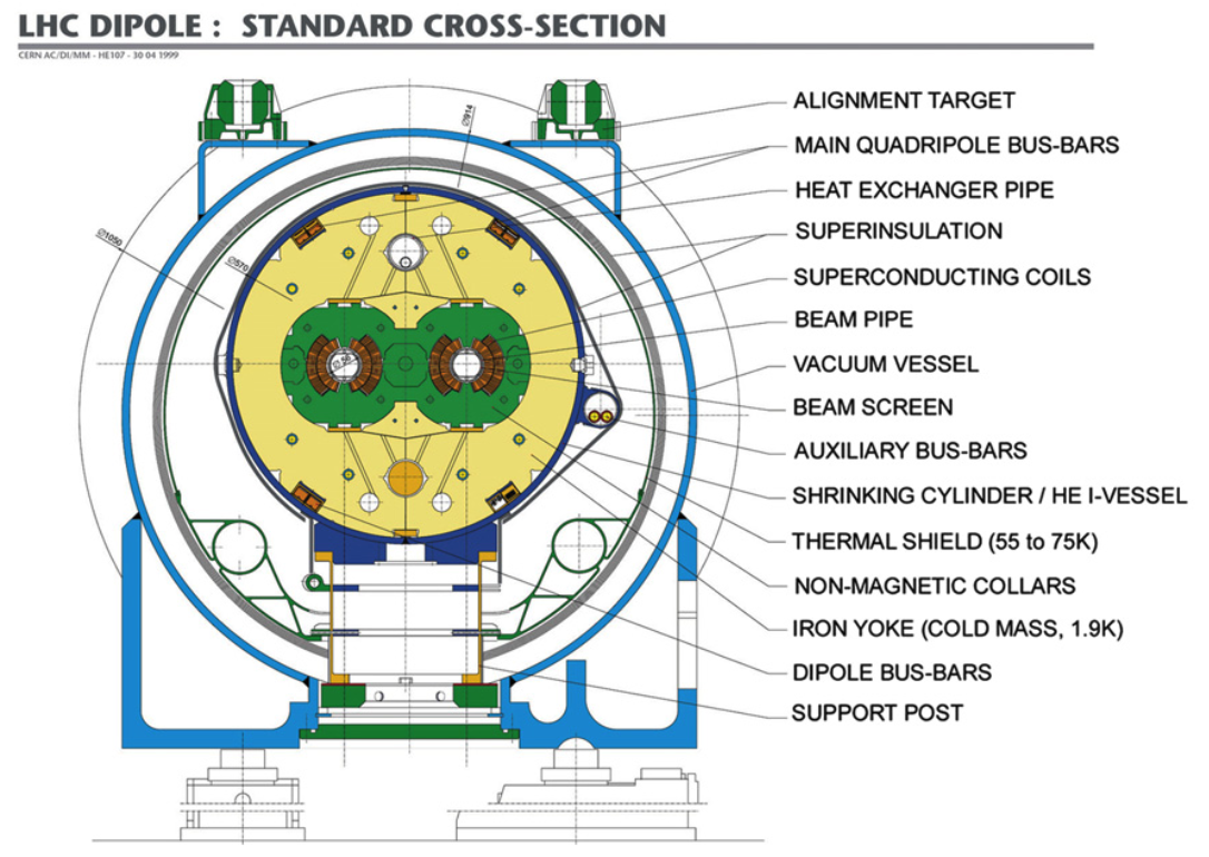
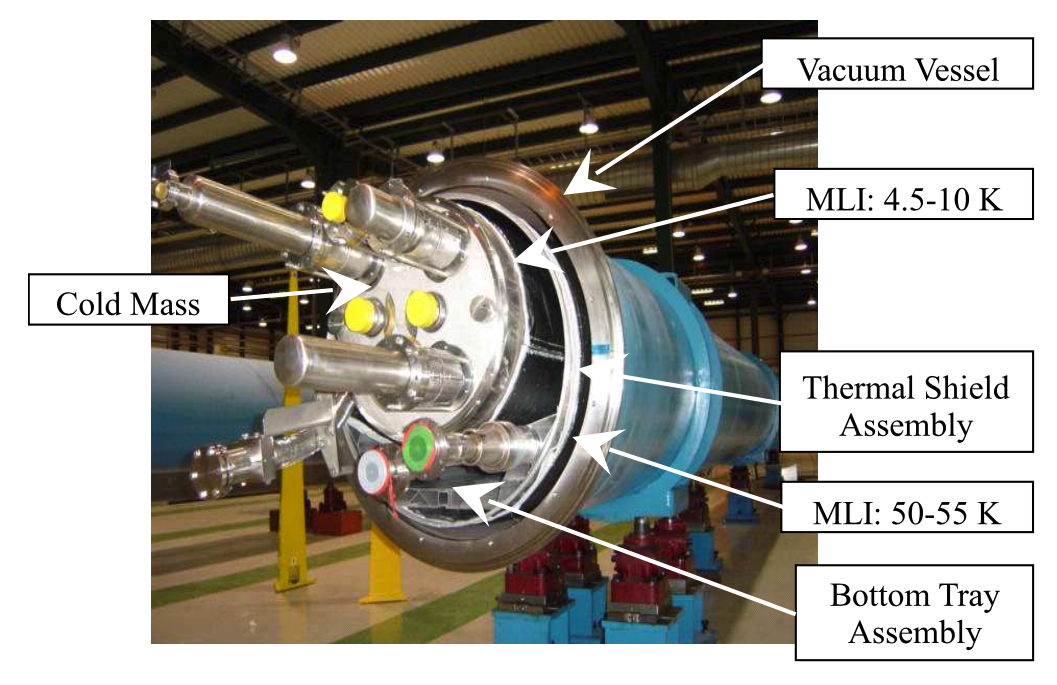
Unlike particle-antiparticle colliders, like the Tevatron, which can accelerate both beams in the same ring with the same magnet system, the proton-proton collisions at the LHC require opposite magnetic fields for the beams before their collision. The benefit, of course, is the ease of producing protons compared to antiprotons, allowing for far higher luminosities. Due to the small 3.7 internal diameter of the existing LEP tunnel, it was not possible to install two separate rings for the two counter-rotating beams; instead, a twin-bore magnet design [171] was chosen to accommodate both in the same ring (Figure 5.4) with two separate vacuum chambers and superconducting coils.
A total of 1,232 such superconducting NbTi dipole magnets are installed around the ring to maintain the circular trajectory of the protons, as well as 392 quadrupole and higher multipole-order magnets to focus the beams. The maximum beam momentum is limited by the bending radius () and the bending field strength () of the dipole magnets, as [34]:
|
| (5.1.1) |
For the LHC tunnel, is ; hence, to achieve 7 protons, the dipole magnets were designed to achieve a field strength of 8.33 (requiring liquid helium cooling to a temperature of 1.9 to maintain superconductivity). However, due to imperfections in some magnets, the LHC initially operated at 3.5–4 per beam in Run 1 (2010–2012), then 6.5 in Run 2 (2015–2018), and currently 6.8 in Run 3 (2022–2026).
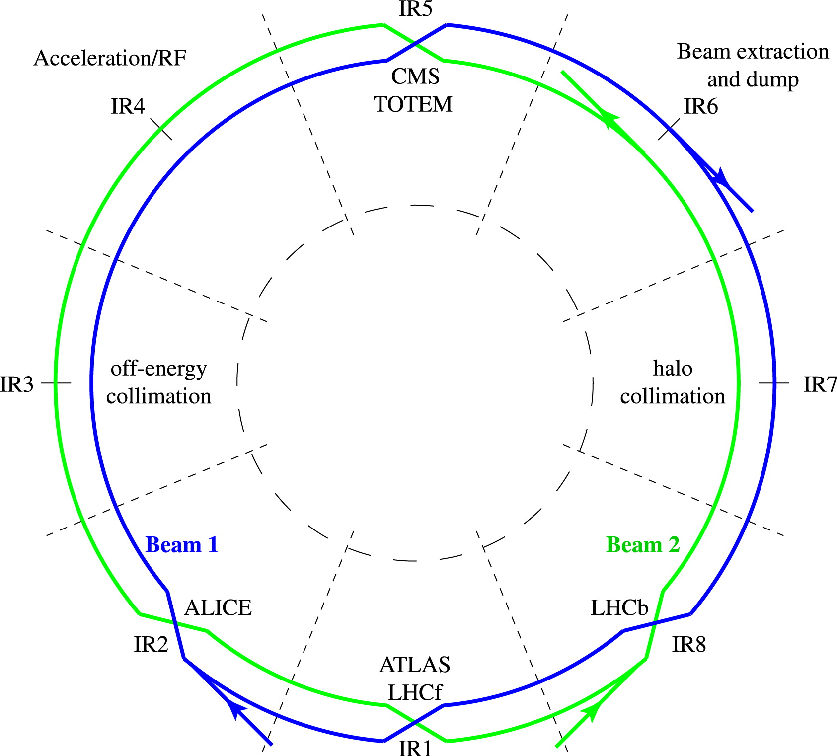
The LHC layout comprises eight arcs and eight long straight sections. The two beams are diverted and collided in four of the straight sections, called “interaction points” (IPs), where the detectors are located (Figure 5.5). The other four straight sections are used for utilities, such as the beam dump and collimation systems.
The protons are accelerated and collided in “bunches” of protons each, with a separation of 25 between bunches. The greater the number of protons per bunch and frequency of bunches, the greater the total luminosity of the collider. Each bunch is accelerated and phase-focused longitudinally by a series of 16 superconducting radiofrequency (RF) cavities into separate “RF buckets”. The RF-frequency of the cavities is 400, corresponding to a theoretical minimum spacing in time of 2.5 between RF buckets / bunches. The LHC opts for the 10-bucket spacing of 25 to avoid “parasitic” collisions between bunches [34]. With this spacing, the maximum number of bunches in the ring is 2808.
