

6.1 Overview
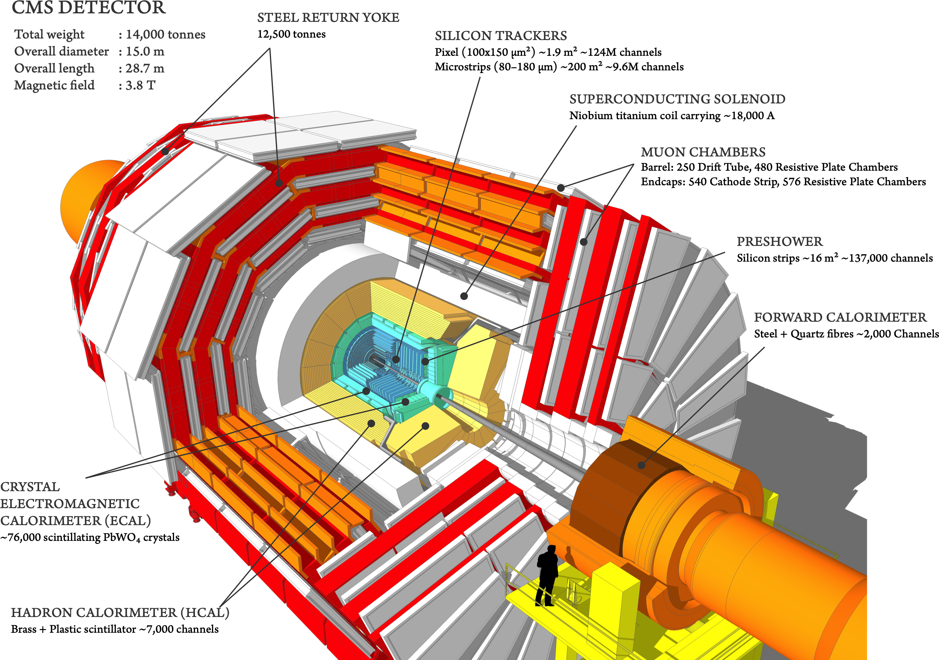
The experimental apparatus used in this dissertation is the Compact Muon Solenoid (CMS) detector (Figure 6.1), one of the two general-purpose detectors at the LHC. It is uniquely characterized by its strong, superconducting 3.8 solenoid magnet, around which are arranged several subdetectors to measure the properties of particles produced in collisions at the LHC. Inside the solenoid, it contains an all-silicon tracker, to measure the momenta of charged particles and identify the collision vertex, and lead-tungstate crystal electromagnetic and brass and scintillator hadronic calorimeters to measure the energy of particles interacting through the electromagnetic and strong forces, respectively. Finally, outside the solenoid are gas-ionization detectors, interleaved with steel flux-return yoke plates, to track muons.
The CMS detector design was strongly motivated by the potential for discovery of the Higgs boson as well as new physics at the energy scale. Specifically, the original design requirements were [46]:
- Strong muon identification and momentum resolution, as well as good charge determination below ;
- High charged-particle momentum resolution and reconstruction efficiency;
- Efficient triggering and good offline reconstruction of -leptons and -jets;
- Strong and hermetic electromagnetic energy resolution for photons and electrons;
- Good missing transverse energy (MET) and jet mass resolutions.
In addition to the above, the detector also had to be robust against the high radiation environment and pileup at the LHC, as well as have a powerful online event selection system, called the trigger, to reduce the high raw 40 data rate to something manageable for offline storage and analysis.
To satisfy the latter, events of interest in CMS are selected using a two-tiered trigger system. The first level (L1) uses custom hardware processors and information from the calorimeters and muon detectors to select events at a rate of around 100 within a fixed latency of 4 [173]. The second level, known as the high-level trigger (HLT), consists of a farm of processors running a version of the full event reconstruction software optimized for fast processing and reduces the event rate to around 1 before data storage [174]. Both online and offline, the raw detector signals are processed and reconstructed first locally as hits in the individual subdetectors, then as tracks and calorimeter clusters, and finally as physics objects such as electrons, muons, jets, and missing energy using the particle-flow (PF) algorithm [48].
As we describe below, the CMS detector was able and continues to meet these ambitious requirements. The CMS collaboration not only discovered the Higgs boson in 2012 [149], but also has since performed a wide range of measurements of the Higgs sector and the SM as well as searches for diverse new physics, such as those described in this dissertation.
Looking ahead, however, the upcoming high-luminosity era of the LHC (Chapter 5.2) will bring forth considerable new challenges to the detector, with significantly higher radiation levels, occupancies, and pileup. To overcome them, nearly all CMS subdetectors will undergo a major upgrade after Run 3, known as the Phase-2 upgrade [43]. The L1 trigger latency will be increased from 4 to 12.5 and the rate from 100 to 750, with an HLT rate of up to 10, to cope with the increased data rates (as well as incorporate tracking information at L1 for the first time) [175].
Along with this, the Phase-2 upgrade includes the addition of new timing layers and the high granularity endcap calorimeter (HGCAL), which is notable not only for its ambitious design, but also the computational challenges it poses in detector simulation and reconstruction. These challenges are a major motivation for the work described in Part IV, exploring machine learning innovations to accelerate these simulations in CMS.
In this chapter, we first introduce general concepts behind particle detectors in Section 6.2, before describing the individual CMS detector components in Section 6.3. The detector reconstruction and performance, as well as the PF algorithm is then discussed in Section 6.4. We conclude with the Phase-2 upgrade of CMS in Section 6.5, including the HGCAL in Section 6.5.4.
Coordinate system
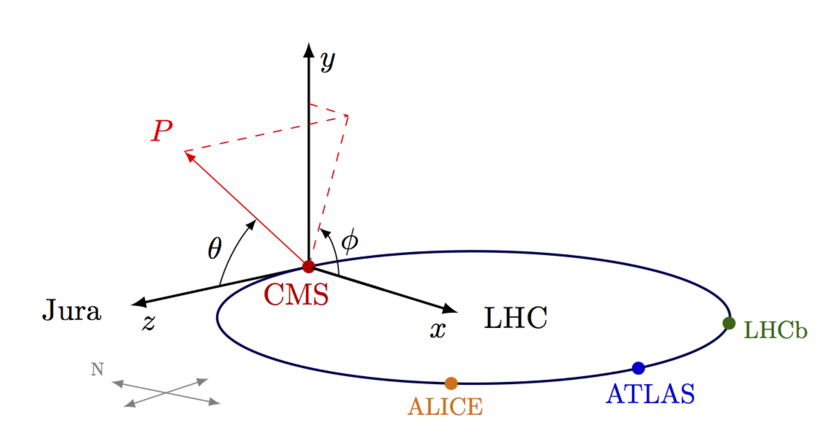
The CMS detector uses a coordinate system illustrated in Figure 6.2, with the origin set at the interaction point within the detector. The -axis is oriented toward the center of the LHC ring, the -axis is perpendicular to the plane of the LHC ring, and the -axis is parallel to the beamline. The azimuthal angle is measured in the - plane, relative to the -axis and the polar angle in the - plane, relative to the -axis. Typically, is converted to the pseudorapidity , which has a more useful scale for describing high energy collisions, and the angular separation between two particles is quantified using the variable . Finally, the transverse component of vectors, such as the transverse momentum , are defined as projections onto the - plane.

