

6.3 CMS detector components
6.3.1 The magnet
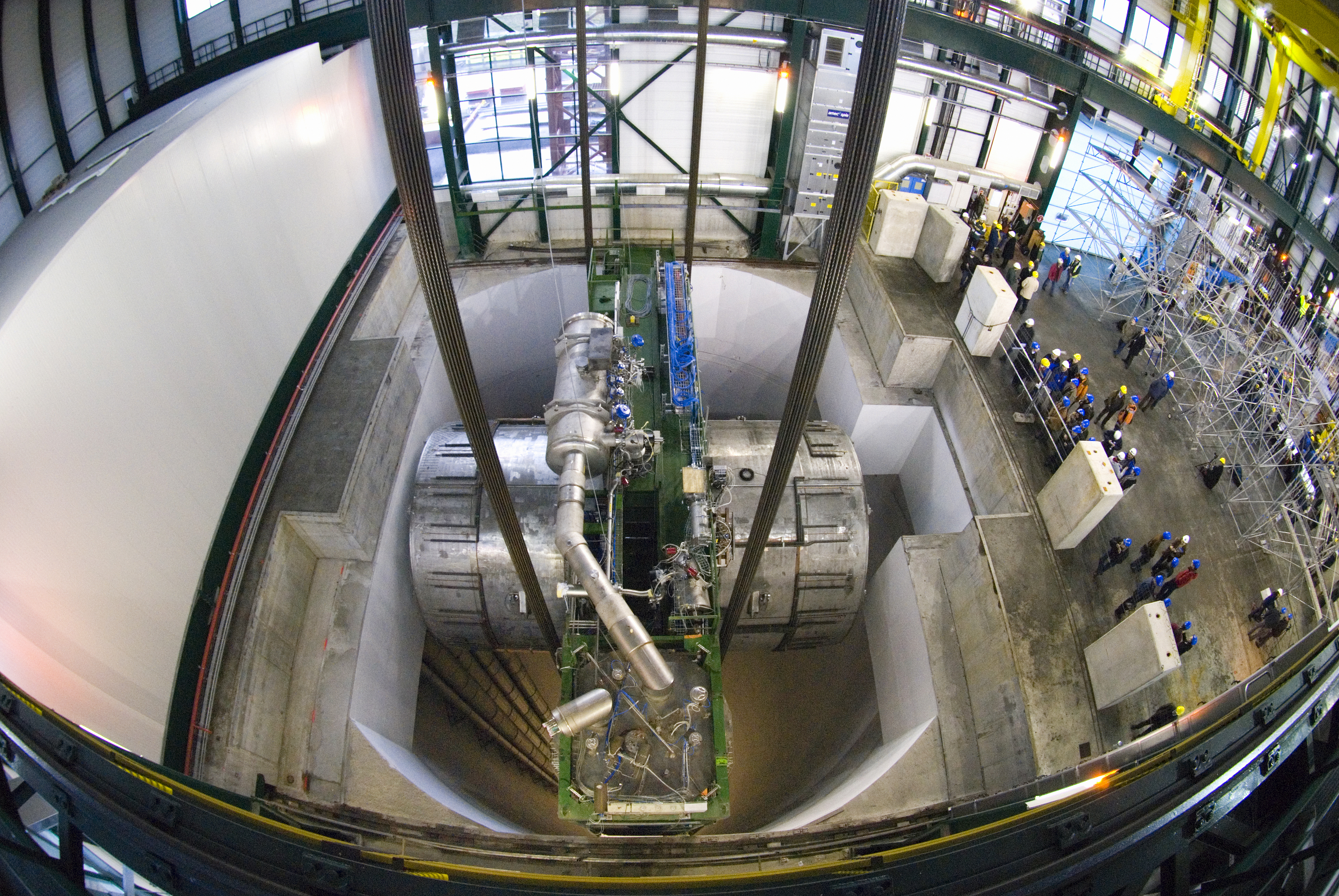
The defining characteristic of the CMS detector is its strong solenoid magnet, with a bending power (Figure 6.5). Its large diameter and length accommodate not only the tracker for momentum measurements, but also the calorimeters in order to reduce the material in front of them. The strength of the magnet was chosen to allow precision measurements of charged-particle momenta and to achieve a target resolution of 10% for 1 muons.
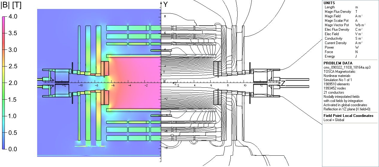
As shown in Figures 6.1 and 6.4 in red, the solenoid is additionally surrounded by massive layers of steel “return yoke”, weighing 12,000 tonnes in total, for several complementary reasons: (1) it confines the magnetic field, improving the efficiency and safety of the detector, by providing a low-reluctance path for the magnetic field lines to return to the solenoid; (2) it is interleaved with the CMS muon system and provides a residual magnetic field for muon tracking; (3) it absorbs the remaining particles not been completely contained by the calorimeters; and, finally, (4) it provides structural support to the detector. The resulting magnetic field throughout CMS is shown in Figure 6.6, where we can see a uniform field within the solenoid and an field in the return yoke.
6.3.2 Tracker
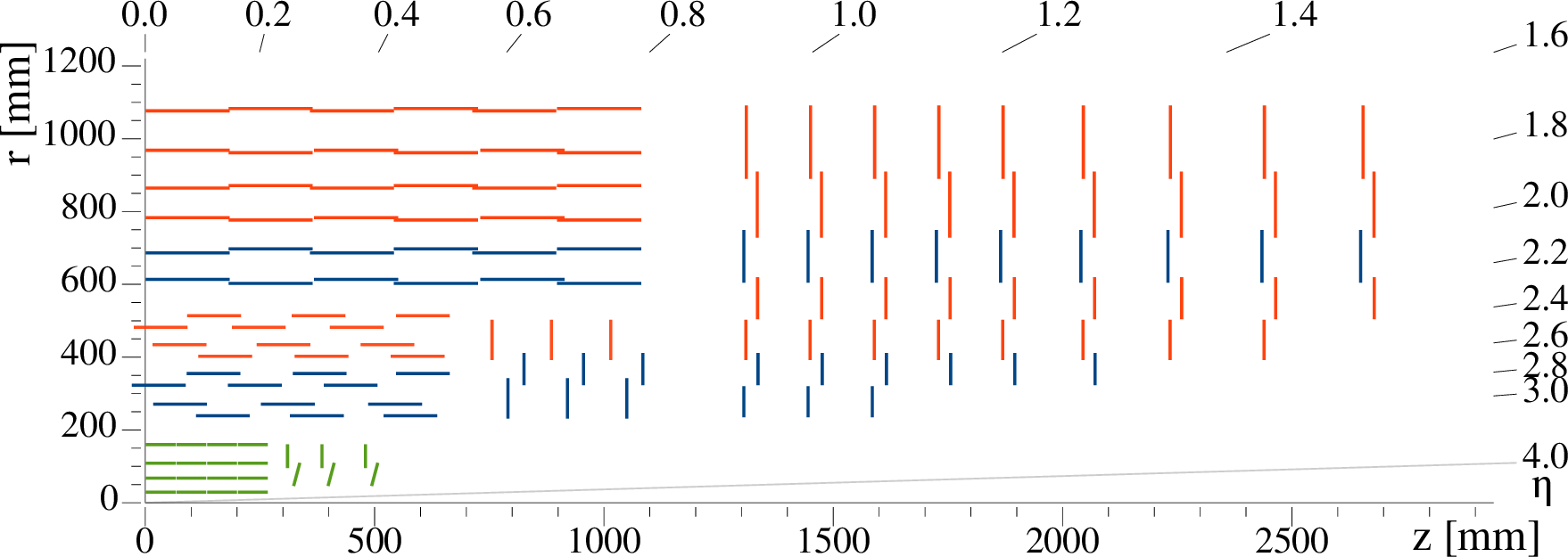
The CMS tracker is designed to achieve the key detector requirements of strong charged-particle momentum resolution and efficient online and offline and -jet reconstruction. It must additionally operate at a high efficiency at the expected average pileup rate of 20-60 collisions per bunch crossing in Runs 1–3 of the LHC. To do so, as illustrated in Figure 6.7, it comprises relatively small and granular silicon pixel layers close to the interaction point for precise vertexing, followed by larger silicon strip layers. The tracker has an overall diameter of 2.5m and length of 5.8m, and is composed of a separate co-axial “barrel” region and two “endcap” regions perpendicular to the beamline, to provide pseudorapidity coverage of .
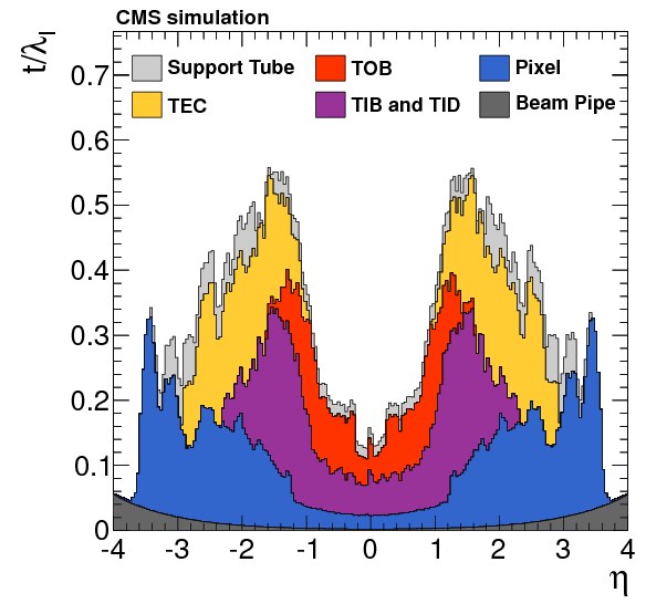
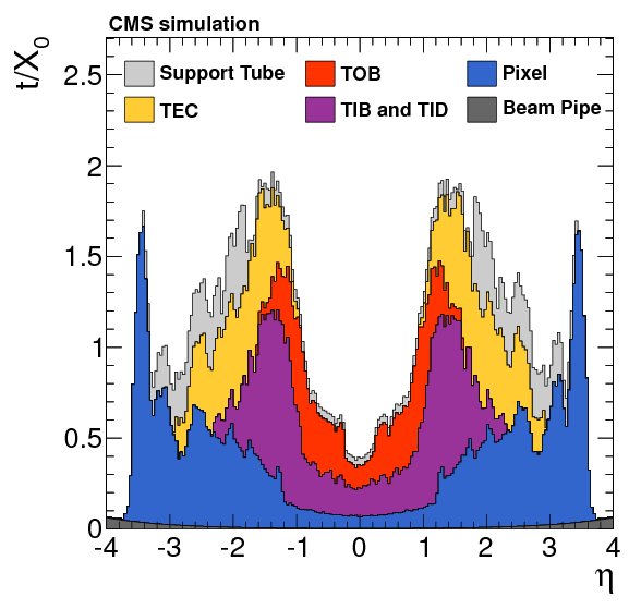
Silicon has several advantages for tracking detectors: it can be made radiation hard to be placed close to the interaction point [181]; it has a low ionization energy of ; it can be made thin — the maximum radiation and nuclear interaction lengths over the entire CMS tracker are around and respectively (Figure 6.8); it is naturally abundant and widely used in the semiconductor industry; and it can be easily patterned to small dimensions for high granularity. This is why, as discussed in Section 6.3, silicon has gained popularity in particle physics, with CMS being the first to use it for the entire tracker.
The pixel tracker includes three barrel layers at radii of 4.4, 7.3, and 10.2 and two pairs of endcap disks at and . It contains a total of 1440 modules and 66 million pixels, of size (or “pitch”) , and thickness . The planar position of the sensor provides a third position coordinate as well. The pixel tracker yields an overall hit position resolution of – in the transverse direction — in the barrel — and – in the longitudinal direction — in the barrel. The pixel orientation is optimized most for resolution, as that is the plane in which charged particles bend from the CMS magnetic field.
Silicon strip modules are longer than pixels, providing high granularity only in one axis, but are more cost-effective; hence, they are used in the outer layers of the CMS tracker, which require a much larger area of coverage: of active coverage versus for the pixels. The strip tracker has 10 barrel layers and three small and nine large endcap disks, with a total of 15,148 modules and 9.3 million strips. It contains two types of strip modules: standard “single-sided” modules as well as “double-sided“ modules mounted back-to-back at a stereo angle to effectively allow pixel-like 2D measurements as well, albeit at a lower granularity.
The strip modules in the barrel are aligned parallel to the beamline with a pitch ranging from –, while those in the endcaps are mounted in the radial direction with a pitch of –. Overall, the strips in the inner barrel and disk layers provide an resolution of –, while the outer layers provide –.
6.3.3 ECAL
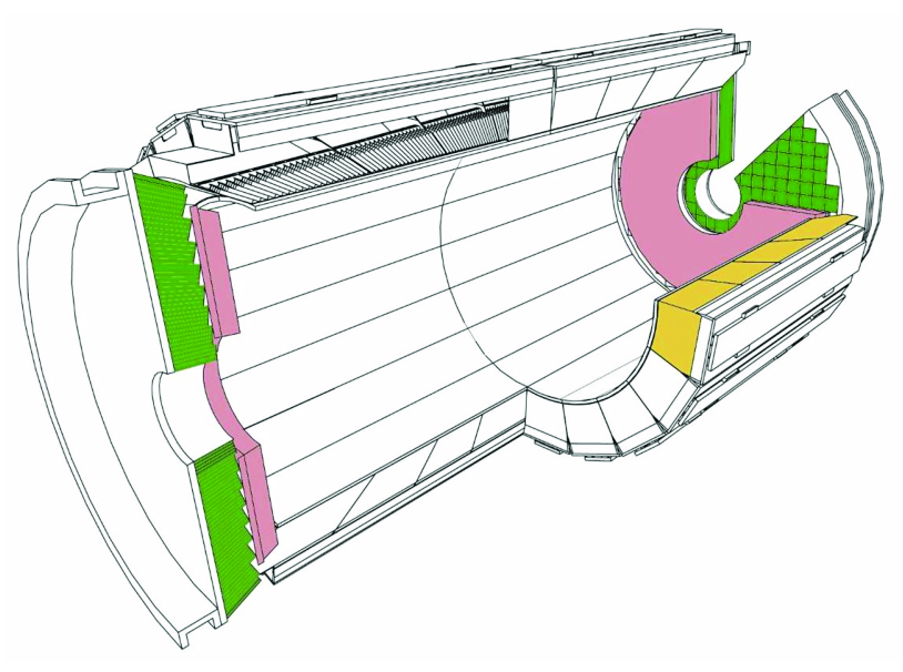
The CMS electromagnetic calorimeter (ECAL) (Figure 6.9) was designed to precisely measure energies of electrons and photons. It was particularly optimized for sensitivity to the Higgs-to-two-photon decay channel, which proved crucial to the discovery of the Higgs boson [149].
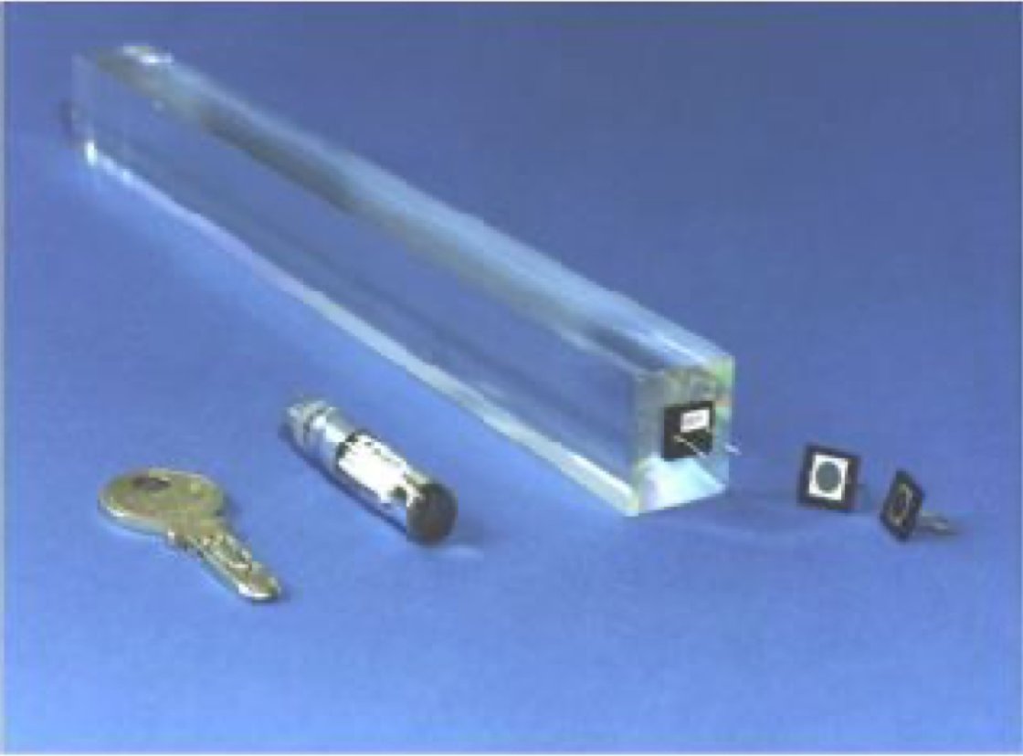
The ECAL is a homogeneous calorimeter made out of 75,848 lead-tungstate (PbWO) crystals (Figure 6.10), which are a type of highly transparent scintillators. PbWO was chosen for its high density (8.28), short radiation length (), and small Molière radius (), which allows for a compact calorimeter with fine granularity. Additionally, its fast scintillation response () allows distinguishing between “out-of-time” (OOT) pileup — particles produced from adjacent bunch crossings — and particles from the primary interaction [183]. The scintillation light is detected by photodiodes glued to the back of each crystal.
Like the tracker, it has a barrel region, covering , and two endcap regions for . They have thicknesses of and , respectively, and a total nuclear interaction length of around 1. This is sufficient to contain > of the energy of electrons and photons, and causes around two thirds of charged hadrons to shower in the ECAL as well.
Additionally, the ECAL includes a “Preshower” sampling calorimeter in the endcap regions, which comprises two layers of of lead to initiate electromagnetic showers, interleaved with active silicon strip detectors for measurements. The purpose of the Preshower is primarily to distinguish between single photons and neutral pion decays into two, close-by, photons in the forward regions, whose energy deposits in the ECAL would otherwise overlap significantly.
6.3.4 HCAL
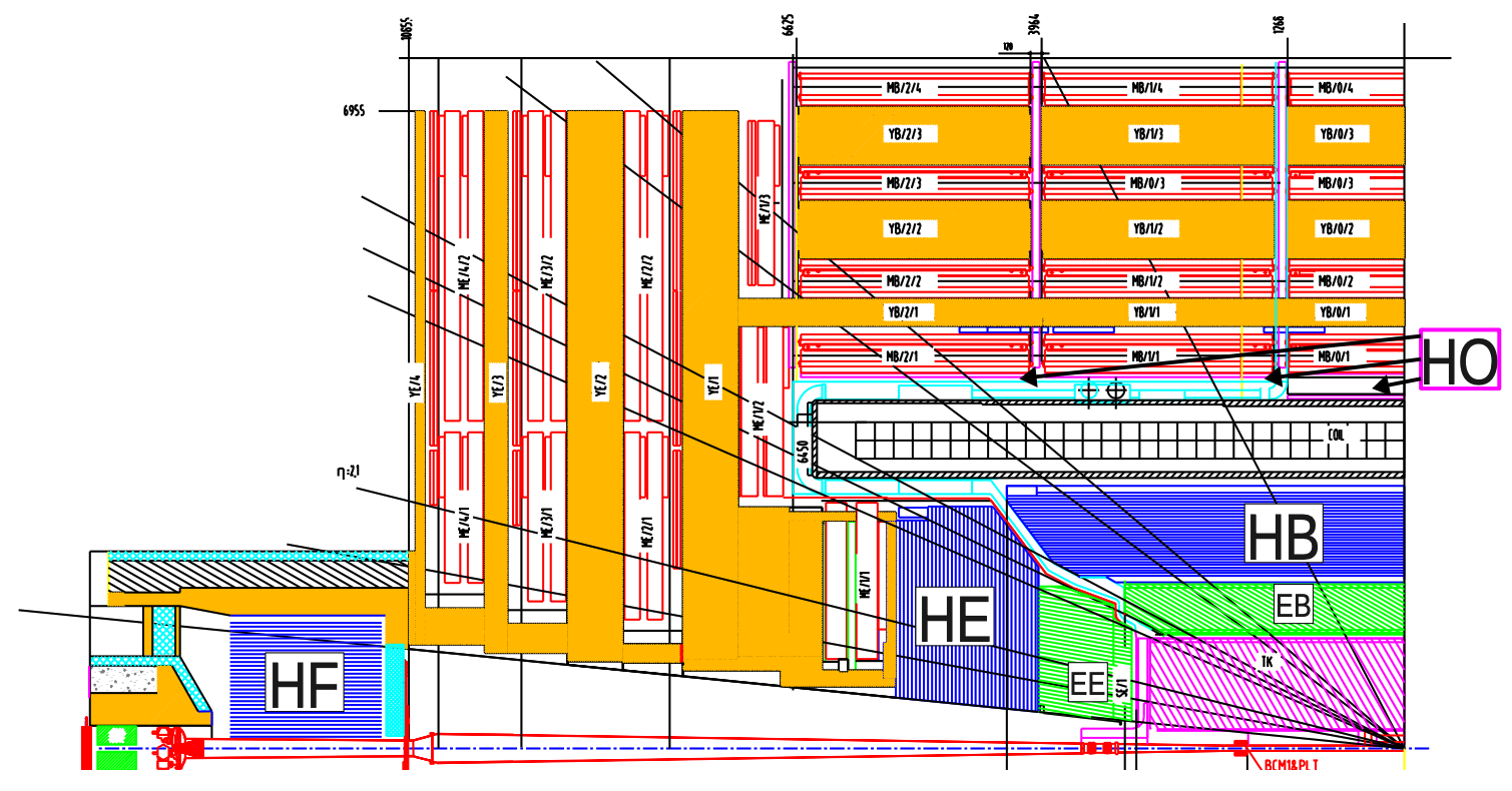
The CMS hadronic calorimeter (HCAL) sits roughly outside the ECAL and is designed to measure the energies of neutral and charged hadrons. It is composed of four major sections: the HCAL barrel (HB), the HCAL endcap (HE), the HCAL outer (HO), and the HCAL forward (HF) (Figure 6.11). Due to their much greater volume compared to the ECAL, the HB, HE, and HO are all chosen to be sampling calorimeters, with alternating layers of absorber material and plastic scintillator. The HF extends the pseudorapidity coverage of CMS up to and is a steel and quartz-fiber Cherenkov calorimeter.
The HB has 14 total layers of brass absorbers and scintillators, with additional steel front and back plates, covering [46]. Due to its radial constraints, with the ECAL and magnet on either side, it has a thickness at of only , with the ECAL adding another .
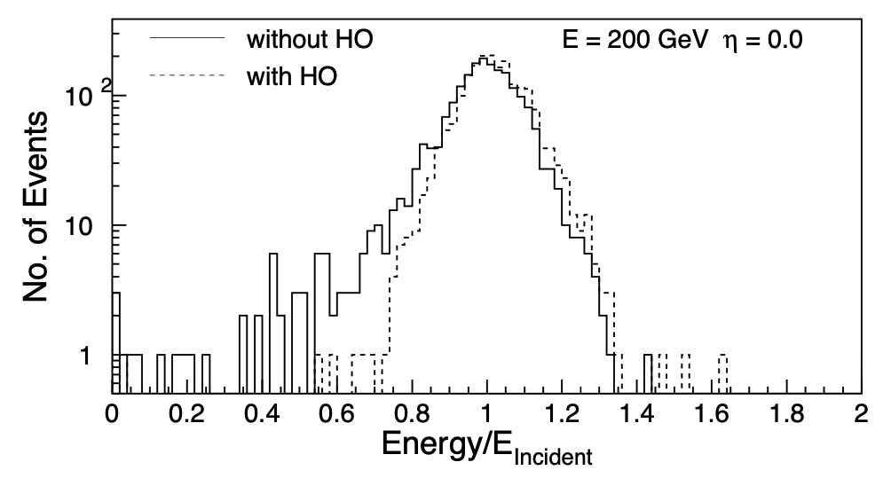
To capture the remaining “tails” of hadronic showers in the barrel region, the HO is placed outside the solenoid. It uses the same scintillators and electronics as the HB, but uses the magnet and return yoke materials themselves as absorbers, adding up to more of material. Figure 6.12 demonstrates that the HO is crucial for capturing the entire energy of hadronic showers: without it, we see an excess of events with the measured energy of hadrons lower than their incident energy, implying a loss of energy with the HB alone.
The HE covers the pseudorapidity range and has 18 layers of brass and scintillators, for a total length of including the ECAL. The granularity of both the HB and HE for is in -, while for in the HE it increases to .
The HF is placed 11.2 from the interaction point to cover the very forward range . Its primary design constraints are the extremely hostile radiation levels in the high-rapidity region, and hence uses steel absorbers and quartz fibers that are radiation hard [184]. It contains of absorber material in each endcap, and measures energy through Cherenkov light emitted by charged particles moving through the longitudinal quartz fibers. It is hence more sensitive to the electromagnetic component of showers.
The HF is important in measuring the energy of an event hermetically and, thereby, the missing energy as well. Moreover, it is crucial in identifying highly forward jets like those produced through VBF-production of Higgs bosons, an important production-mode measured in this dissertation (see Chapters 4.3 and 14).
6.3.5 Muon system
As implied by its name, detecting muons with high efficiency and precision was a key consideration in the design of CMS. This is because of their unique signature compared to the other particles in Table 6.1, the possibility of Higgs discovery in the channel, and the relatively low isolated-muon background at the LHC. Indeed, the channel was crucial to the discovery of the Higgs boson [149].
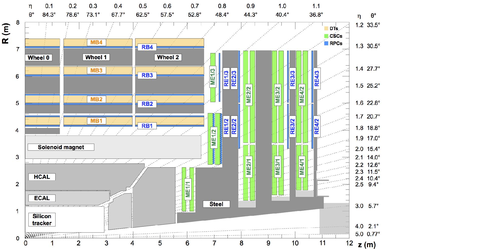
Muons are detected through a combination of the silicon tracker inside the solenoid, and dedicated gas ionization chambers for tracking muons outside the solenoid, covering a total pseudorapidity range of . The muon system, being the outermost subdetector, needs to cover the largest amount of area — around 25,000m of detector layers — and hence uses gaseous detectors to minimize cost while maintaining reliability and robustness. Three types of gas detectors are used: drift tubes (DTs) in the barrel region, cathode strip chambers (CSCs) in the endcap regions, and resistive plate chambers (RPCs) in both, all housed between the steel flux return yoke layers, as shown in Figure 6.13.
Because of the lower radiation and background levels expected in the barrel region, standard DT chambers are used, which are known to have excellent spatial and timing resolution while remaining relatively inexpensive. There are four muon barrel (MB) radial layers, or “stations”. The innermost three each contain eight chambers measuring the position in the - plane and four measuring the coordinate. The outermost contains only the - chambers.
Each chamber comprises several layers of long aluminum drift cells, which have a transverse area of and are filled with a mixture of argon (Ar) and carbon dioxide (CO) gas. They contain a single anode wire in the center, and the drift time of the electrons to the wire is used to calculate the muon position. The average single-cell spatial resolution has been measured to be , with a combined per-chamber resolution of in - [46]. DT chambers also provide a time resolution on the order of nanoseconds, allowing local, independent triggering on muon .
The endcaps are subject to much higher radiation and hence use the more radiation-hard CSCs, which offer fast response times and fine segmentation as well but are more expensive. They can also tolerate the non-uniformity of the magnetic field in the endcap regions (see Figure 6.6). There are four muon endcap (ME) stations on each side, which are divided into “rings” in the -direction, and labeled as ME1/2 for the second ring in the first station and so on.
The endcap muon system contains a total of 468 CSCs: 216 in ME1, 108 in ME2 and ME3 each, and 36 in ME4. A single CSC is composed of six layers of multi-wire proportional chambers, each containing several anode wires spaced between 2.5–3.2 apart and 80 cathode strips to read out position in the - plane [185]. The CSCs overall provide a spatial resolution in - of in ME1/1 and ME1/2 and elsewhere, with a time resolution of < [46]. This means CSCs, like the DTs, independently allow local triggering on muon with good efficiency and background rejection.
Finally, RPCs are included as well in both the barrel and endcap regions to provide complementary triggering capabilities. RPCs are double-gap chambers operated in avalanche mode, which means they primarily offer fast timing information, with around resolution, but relatively poor spatial resolution [186]. There are four RPC barrel (RB) and three RPC endcap (RE) stations, complementing the DTs and CSCs with faster timing information and allowing the muon trigger threshold to be lowered.
